


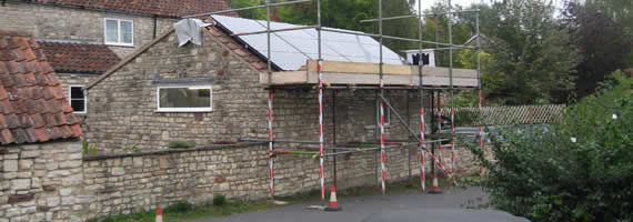
2.88Kwp Sanyo Array using SMA SB3000 inverter, Camerton, Bath
LIGHTNING
General Guidance
Lightning is one of the most awesome phenomena of nature and produces both electrical and magnetic fields which vary with distance, frequency and time.
Strokes of lightning coming from thunder clouds to the ground may strike anywhere. The peak currents average 20,000 amps and may reach 200,000 amps. If lightning strikes a building; substantial structural damage can be caused and fires may be started. Protection should be provided, however, in cases where the likelihood of lightning striking is greater than normal or where the consequences would be particularly unfortunate.
Lightning can cause damage either from a direct strike or from surges due to a nearby strike. Induced surges are the more likely cause for lightning damage in the majority of installations. A nearby strike can induce surges on both the PV array conductors or the AC cables leading to the building. Strikes on or near overhead power cables can also cause surges miles away from the lightning strike itself.
The relevant British Standard to be consulted for lightning protection is BS6651.
General guidance for photovoltaic systems is provided in BS EN 61173 1995 IEC 1173 – 1992.
Lightning Protection Systems
Lightning Protection Systems (LPS) have three major parts: air terminations, down conductors and earth terminations.
Air terminations are located over the highest points of the building to intercept lightning strokes before they strike the fabric itself. A single point air termination is considered to give a zone of protection defined by cone the apex of which is formed by the air termination and the base of which has a radius equal to the height of the air termination.
A pitched roof can be protected by an air termination running along the ridge while a flat roofed building would require an air termination round its perimeter. In buildings with roofs at several levels protection to the lower levels will only be required where they project beyond the zones of protection provided by higher air terminations.
Down conductors must be provided to carry the currents arising from lightning strikes from air terminals down to earth terminations. They should follow a simple path down the buildings. Bends are permissible but re-entrant loops should be avoided. A building of up to 100 m2 in plan can be served by one down terminal and one additional down terminal should be provided for every 300 m2of area in excess of 100 m2.
Earth terminations are required to give a low resistance path to earth for the current. They should be near the bottoms of down conductors and the total resistance of the lightning protective system to earth should not exceed 10 ohms. A system having a single downconductor and earth termination must have a resistance, not exceeding this value. In multiple systems individual resistances may be higher provided the combined resistance does not exceed 10 ohms. The preferred form of earth terminations is metal rods driven into the ground.
If the building on which photovoltaics are to be installed is provided with a lightning protection system, the photovoltaic metallic parts, usually the mounting structures, may need to be linked into this earthed system. This is described as equi-potential bonding. If the panels have frames the panels should be bonded together using devices like earth bridges to provide a continuous metallic path. This requirement will depend upon the separation of the components of the two systems.
Should lightning hit a building with an LPS the energy will have a clear path to earth and travel down this route to a safe point to dissipate. That prevents “flash over” of this huge amount of energy trying to find the path of least resistance and crossing over to the PV metal frame. This could create sparks / fires with all the consequential associated hazards. The LPS will probably be bonded to the main building earth or, in the case of a PME system, may rely entirely on separate earth spikes.
Lightning and PV Systems
General Principals
To protect any PV system from a direct lightning stroke is practically impossible, due to the amount of energy which can potentially be transferred.The voltage induced in a PV module by a near miss lightning stroke depends on the
magnetic coupling (M) between a lightning strike and the module, and the rate of change of the lightning current.
When assuming a maximum coupling between surface of the PV module and the magnetic field, the voltage can be calculated with:
Uinduced=Adb/dt=mdi/dt
Where A is the surface area, dB/dt the rate of change of the magnetic field, M the mutual coupling between the magnetic field and the PV module and di/dt the rate of change of the current.
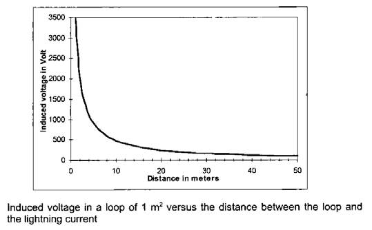
As an illustration, the diagram below shows the peak value of induced
voltage an a loop of 1m² as a function of the distance between the loop and a 25 kA/μs lightning strike.
The possible overvoltage induced within a system, due to indirect lightning strokes can be minimised, providing some important rules are adhered to. The main objective in the mitigation of these overvoltages is to reduce the loops between the AC wiring, DC wiring and grounding structure.
Two factors need to be considered when examining lightning protection for a grid
connected PV system:
• Has the installation led to an increased risk of lightning damage to the site where the PV system is installed?
• Should lightning protection be specified to safeguard the system itself?
Assessing any increased risk to the site
It seems generally accepted that the installation of a typical roof mounted PV system, presents a very small increased risk of a direct lightning strike. However, this may not necessarily be the case where the PV system is particularly large; where the PV system is installed on the top of a tall building; where the PV system becomes the tallest structure in the vicinity; or where the PV system is installed in an open area such as a field.
Long cables constitute a particular high risk in terms of induced voltages, and so all DC cables should be installed to provide as short runs as possible, and positive and negative cables of the same string, or main DC supply, be bundled together avoiding the creation of unnecessary cable loops in the system. This requirement for short runs and bundling includes any associated earth / bonding conductors.
Long cables (eg PV main DC cables over about 50m.) should be specified to run in and be installed in earthed metal conduit or trunking. These measures will act to both shield the cables from inductive surges and also by increasing inductance, attenuate surge transmission. It must be remembered however that there is the need to allow any water or condensation that may accumulate in any conduit or trunking to escape through properly designed and installed vents.
The nature of the site should also be considered. Systems in a location such as a petrol refinery for example, would need careful consideration.
Where there is a perceived increase in risk of direct strike as a consequence of the
installation of the PV system, specialists should be consulted with a view to installing a separate lightning protection system. A full risk analysis would be performed - taking into account factors such as soil resistivity, array dimensions, length of overhead cables, flash density for the area, geographic factors, ground profile and terrain.
Assessing the risk to the PV system
A similar risk assessment to that outlined above should also be applied to safeguarding the PV system itself. While it may be considered that the PV system may not lead to an increased risk to the site as a whole, system components are expensive (particularly inverters) and some form of protection may be considered appropriate.
Many if not most grid connect inverters have some form of in-built surge suppression.Engineers should become familiar with the protection afforded by the units they routinely specify. SMA Sunny Boy inverters, for example, have varistors connected between DC positive & earth and DC negative & earth. It is to be noted however, that SMA specifically exclude lightning damage from the inverter guarantee. In certain circumstances it may be considered necessary to specify additional surge protection to that contained within the inverter.
Considerations for sites with separate lightning protection
• Mount system components away from lightning rods & down leads. For example, an inverter should not be mounted on an inside wall that has a down lead running just the other side of the brickwork on the outside of the building.
• The PV array and frame may require bonding to the lightning protection system. This will depend upon the separation of the components of the two systems. A formula for determining this requirement can be found in BS6651, though perhaps the better route would be to consult the installers of the lightning protection system.
• Where bonding to the lightning protection system is required, supplementary equipotential bonding will also be required.